X10のメカニズム
X10 communicates between transmitters and receivers by sending and receiving signals over the power line wiring. These signals involve short RF bursts which represent digital information.
X10は、電力線を経由して信号を送受信することによってトランスミッタとレ シーバの間で通信を行うものです。これらの信号は、短いFRバースト信号を含 んでおり、デジタル情報として表現されます。
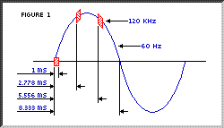
X10 transmissions are synchronized to the zero crossing point of the AC power line. The goal should be to transmit as close to the zero crossing point as possible, but certainly within 200 microseconds of the zero crossing point. The PSC05 provides a 60 Hz square wave with a maximum delay of 100 μsec from the zero crossing point of the AC power line. The maximum delay between signal envelope input and 120 kHz output bursts is 50 μsec. Therefore, it should be arranged that outputs to the PSC05 be within 50 μs of this 60 Hz zero crossing reference square wave.
X10トランスミッションは交流電源線のゼロ交差点と同期にします。 その目的は、可能な限り正確にゼロ交差点で転送を行う為です。 PSC05は、ゼロ交差点から最大100μ秒で60Hzの方形波を提供します。 エンベロープ入力信号と、120KHz出力バースト信号の最大遅延は50マイクロ秒 です。 したがって、PSC05の出力は、60Hzのゼロ交差参照用の方形波から50マイクロ 秒以内となるようにしなければなりません。

A Binary 1 is represented by a 1 millisecond burst of 120 kHz at the zero crossing point, and a Binary 0 by the absence of 120 kHz. The PSC05 modulates its input (from the O.E.M.) with 120 kHz, therefore only the 1 ms "envelope" need be applied to its input. These 1 millisecond bursts should equally be transmitted three times to coincide with the zero crossing point of all three phases in a three phase distribution system. Figure 1 shows the timing relationship of these bursts relative to zero crossing. .
バイナリの"1"は、ゼロ交差点で120KHzの1ミリ秒のバースト信号として表現さ れ、"0"は、それらが存在しないことを表現します。 PSC05は120KHでその入力を調整し、1msのエンベロープのみが、その入力とし て使用されることになります。 これらの1ミリセカンドのバーストは、三相交流におけるすべての三相のゼロ 交差点と一致するように3回等しく伝えられるべきです。 (訳者:日本の一般家庭で三相交流使うかな?) 図1は、ゼロ交差点比較した場合のこれらのバーストの関連を示すタイミング 図です。
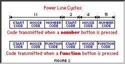
A complete code transmission encompasses eleven cycles of the power line. The first two cycles represent a Start Code. The next four cycles represent the House Code and the last five cycles represent either the Number Code (1 thru 16) or a Function Code (On, Off, etc.). This complete block, (Start Code, House Code, Key Code) should always be transmitted in groups of 2 with 3 power line cycles between each group of 2 codes. Bright and dim are exceptions to this rule and should be transmitted continuously (at least twice) with no gaps between codes. See Figure 2. .
一連のコード送信は電力系列の11サイクルで構成されます。 最初の2サイクルはスタートコードを表します。 次の4サイクルがハウスコードを表して、のこりの5サイクルがナンバーコード (1から16)、またはファンクションコードのどちらかを表します(ON、Off、そ の他) 。 この一連のブロック(スタートコード、ハウスコード、キーコード)は、2つの コードのそれぞれのグループ間での三相交流の2つのグループ内で(訳者:な んだかよく分からん)常に転送されなければなりません。 "Bright"と"Dim"は、これらのルールの例外でコード間でギャップなしで(少 なくとも2回)連続して転送されなければなりません。図2参照
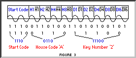
Within each block of data, each four or five bit code should be transmitted in true compliment form on alternate half cycles of the power line. I.E. if a 1 millisecond burst of signal is transmitted on one half cycle (binary 1) then no signal should be transmitted on the next cycle, (binary 0). See Figure 3.
それぞれのブロックのデータの中では、それぞれの4か5ビットコードは電力線 の交互の半周期の真の賛辞フォーム(訳者:Typo?)で伝えられるべきです。 もし、半分サイクルに信号"1"を1ミリセカンドのバーストで伝えるなら、次の サイクルで信号を全く送信してはなりません。 図3を参照してください。
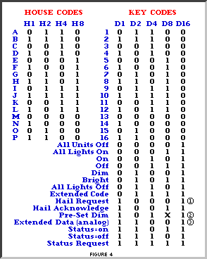
The Tables in Figure 4 show the binary codes to be transmitted for each House Code and Key Code. The Start Code is always 1110 which is a unique code and is the only code which does not follow the true complimentary relationship on alternate half cycles. .
図4の表は、ハウスコードとキーコードのために伝えられるために2進コードを 示しています。 スタートコードはいつもユニークなコードである1110であり、 代替の半周期での逆転しない唯一のコードです。
[1] Hail Request is transmitted to see if there are any X10 transmitters within listening range. This allows the O.E.M. to assign a different Housecode if a "Hail Acknowledge" is received.
[1] 呼びかけ要求(Hail Request)は、リスニング範囲にX10送信機があるか否 かを確認するために伝えられます。 これは、O.E.M.に、もし「呼びかけ要求」 が受信されたのであれば、異なるハウスコードをアサインすることを許可しま す。
[2] In a Pre-Set Dim instruction, the D8 bit represents the Most Significant Bit of the level and H1, H2, H4 and H8 bits represent the Least Significant Bits.
[2] Pre-セットDim指示では、D8ビットは、レベルのMost Significant Bit(MSB)を表します、そして、H1、H2、H4、およびH8ビットはLeast Significant Bits(LSB)を表します。
[3] The Extended Data code is followed by 8 bit bytes which can represent Analog Data (after A to D conversion). There should be no gaps between the Extended Data code and the actual data, and no gaps between data bytes. The first 8 bit byte can be used to say how many bytes of data will follow. If gaps are left between data bytes, these codes could be received by X10 modules causing erroneous operation.
[3] Extended Dataコードの後には、アナログデータ(デジタルへの変換後)を 表すことができるができる8ビットが続きます。 Extended Dataコードと実際のデータ間にはギャップはなく、データバイト間 にもギャップはありません。 バイトのデータがいくつ続くかを言うのに最初の8ビットのバイトを使用する ことができます。 ギャップをデータバイトの間に残すと、これらのコードは、X10モジュールに 誤った操作を引き起こさせるかもしれません。
Extended Code is similar to Extended Data: 8 Bit bytes which follow Extended Code (with no gaps) can represent additional codes. This allows the designer to expand beyond the 256 codes presently available. .
拡張CodeはExtended Dataと同様です: Extended Code(ギャップのない)に続く8ビットのバイトは追加コードを表すこ とができます、設計者に256以上のコード拡張を許容します。
NOTE 1 . X10 Receiver Modules require a "silence" of at least 3 power cycles between each pair of 11 bit code transmissions (no gaps between each pair). The one exception to this rule is bright and dim codes. These are transmitted continuously with no gaps between each 11 bit dim code or 11 bit bright code. A 3 cycle gap is necessary between different codes, i.e. between bright and dim, or 1 and dim, or on and bright, etc.
注意1 X10 Receiver Modulesはそれぞれの組の11のビット・コード送信(各組でギャッ プがない)の間で少なくとも3パワーサイクルの「沈黙」を必要とします。 この規則への1つの例外が"Bright"と"Dim"コードです。 これらは、それぞれの11ビットの"Dim"コードか11ビットの"Bright"コードと ギャップなしで絶え間なく伝えられます。 3サイクルのギャップは、異なるコード間で必要となります。 例えば、"bright"と"dim"、"1"と"dim"と"bright"などです。
NOTE 2. The PSC05 Two-Way Power Line Interface cannot receive Extended Code or Extended Data because these codes have no gaps between them. The PSC05 can only receive standard "pairs" of 11 bit X10 codes with 3 power line cycle gaps between each pair.
注意2 PSC05 2ウェイパワーラインインターフェースは、拡張コードや拡張デー タを受信できません。これらのコードはギャップが存在しないからです PSC05は、それぞれのペアで三相交流のギャップかんで11ビットのX10コードの 「ペア」のみをを受信できます。
NOTE 3. The PSC05 can receive dim and bright codes but the output will represent the first dim or bright code received, followed by every third code received. i.e. the output from the PSC05 will not be a continuous stream of dim and bright codes like the codes which are transmitted.
注意3: PSC05は"dim""bright"コードを受け取ることができますが、出力は、最初の "dim""bright"コードを受け取り、それぞれ受信された3番目のコードが続きま す。 例えば、PSC05からの出力は、転送されたコードのように"dim""bright"のスト リームとはなりません。
A Square wave representing zero crossing detect is provided by the PSC05 and is within 100 &s of the zero crossing point of the AC power line. The output signal envelope from the O.E.M. should be within 50 &s of this zero crossing detect. The signal envelope should be 1 ms (-50μs +100μs). See Figure 5.
ゼロ交差検知を示す方形波は、PSC05によって提供され、交流電源のゼロ交差 ポイントから100μ秒で立ち上がります。OMEからの出力信号エンベロープは、 ゼロ交差検知から50マイクロ秒以内に立ち上がらなければなりません。出力信 号エンベロープは、1msであるべきです。(-50μ秒〜+100μ秒) 図5を参照してください。
Opto-Coupled 60 Hz reference output (from the PSC05) オプトカップラー60ヘルツ参照出力(PSC05から)
Transmissions are to be synchronized to the zero crossing point of the AC power line and should be as close to true zero crossing as possible. The PSC05 is designed to be interfaced to other microprocessor circuitry which outputs X10 codes synchronized to the zero crossing point of the AC power line. It is therefore necessary to provide a zero crossing reference for the O.E.M. microprocessor.
トランスミッションは、交流電源線のゼロ交差点に同期し、できるだけゼロ交 差の近くにあるべきです。 PSC05は、交流電源線のゼロ交差点と同期するX10コードを出力する他のマイク ロプロセッサ回路に接続されるように設計されています。 したがって、O.E.M.マイクロプロセッサのために、ゼロ交差参照を提供する必 要があります。
It is likely that this microprocessor will have its own "isolated" power supply. It is necessary to maintain this isolation, therefore the trigger circuit normally used in X10 controllers is not desirable as this would reference the O.E.M. power supply to the AC power line. It is also not desirable to take the trigger from the secondary side of the power supply transformer as some phase shift is likely to occur. It is therefore necessary to provide an opto-coupled 60 Hz reference
このマイクロプロセッサにはそれ自身の「独立している」電源があるようです。 この独立を維持するのが必要であるので、通常、X10コントローラで使用され るトリガ回路は、これは交流電源へのO.E.M.電源を参照とすることは望ましく ありません。 また、何らかのフェーズシフトが起こしかねない電源変圧器二段側から引くの も望ましくはありません。 したがって、60Hzのオプトカップラーで、リファレンスを提供することが必要 です。
An opto-coupled 60 Hz square wave is provided at the output of the PSC05. X10 codes generated by the O.E.M. product are to be synchronized to this zero crossing reference. The X10 code envelope generated by the O.E.M. is applied to the PSC05 which modulates the envelope with 120 kHz and capacitively couples it to the AC power line.
オプトカプラーの60Hz方形波は、PSC05の出力として提供されます。O.E.M.製 品で提供されるX10コードは、ゼロ交差参照と同期が取られます。O.E.M.で生 成されたX10コードエンベロープは、PSC05に適合します。
Opto-Coupled Signal Input (to the PSC05) オプトプトカップリング信号入力
The input signal required from the O.E.M. product is the signal "envelope" of the X10 code format, i.e.
O.E.M.製品から要求される入力信号は、「封筒」というX10コード形式に関す る信号となります。
High for 1 ms. coincident with zero crossing represents a binary "1" and gates the 120 kHz oscillator through to the output drive circuit thus transmitting 120 kHz onto the AC power line for 1 ms.
ゼロ交差があるコインシデンスは2進の「その結果交流電源に120kHz伝える出力 駆動回路に終えた120kHzの振動子が1つの原稿のために裏打ちする1インチとゲ イツ」を表します。
Low for 1 ms. coincident with the zero crossing point represents a binary "0" and turns the 120 kHz oscillator/output circuit off for the duration of the 1 ms. input. .
ゼロ交差ポイントがあるコインシデンスはバイナリーを表します。「120kHzの 振動子/が1つの原稿入力の持続時間のためにサーキットを出力した0インチと回 転。
Opto-Coupled Signal Output (from the PSC05) オプトプトカップリング信号出力
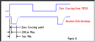
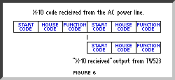
The "X10 received" output from the PSC05 coincides with the second half of each X10 transmission. This output is the envelope of the bursts of 120 kHz received. Only the envelope corresponding to the first burst of each group of 3 bursts is available at the output of the PSC05. See Figures 6, 7, and 8. .
PSC05からの「X10受信」出力は、それぞれのX10トランスミッション の後半と同期します。 この出力は120kHzのバーストエンベロープがが受信されたということです。 3回のバーストのそれぞれのグループの最初のバーストに対応するエンベロー プだけがPSC05の出力で利用可能です。 図6、7、および8を参照してください。
